|
Never Forget |
||||||||||||||||||||||||||||||||||||||||||
|
|
||||||||||||||||||||||||||||||||||||||||||
EngineInteriorExteriorOld Items1C3EL75R62N324237Car InformationThe Society of Automotive Engineers Car EnthusiastsCar Parts Vendors |
2002 Chrysler Sebring Convertible GTC
|
|||||||||||||||||||||||||||||||||||||||||
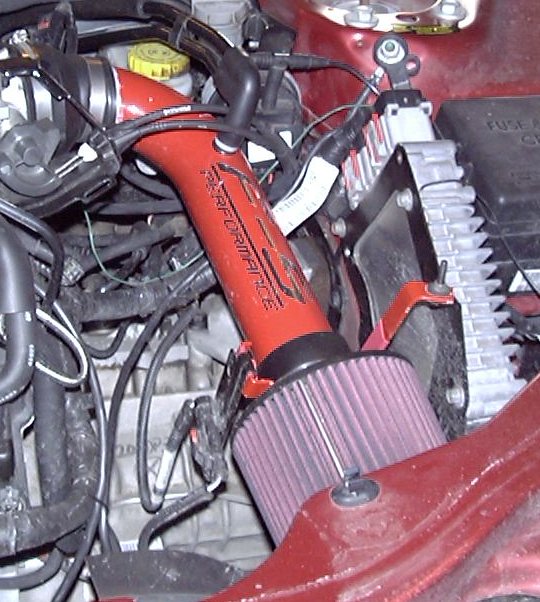 |
| Installation of F-5 Performance Short Ram Induction Tube, Version 2 |
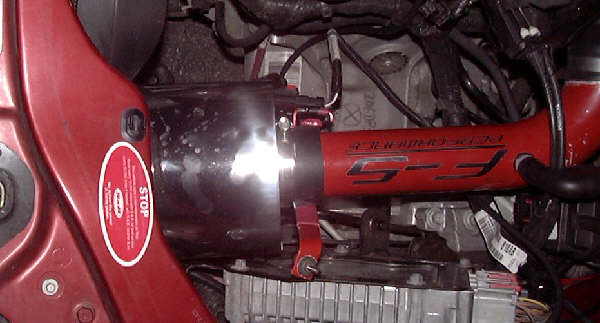 |
| Installation of F-5 Performance Short Ram Induction Tube, Version 3, With Heatshield |
Upgraded Throttle Body
I replaced the throttle body on my engine with a throttle body off of an engine equipped with an automatic transmission. Why? I'll explain below.
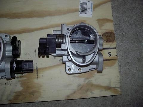 |
| Front view of stock manual TB (plastic wedge partially removed) |
The throttle body for a stock 2.7L engine with the manual transmission has a 64 mm bore. There is a venturi-style restriction before the throttle plate. The plate itself has a plastic wedge on it, which aids in part-throttle control, that sticks out 8 mm from the surface of the throttle plate. The wedge itself is not aerodynamically shaped, so it presents a flow restriction. The effective WOT open area for this throttle body is about 2207 mm^2.
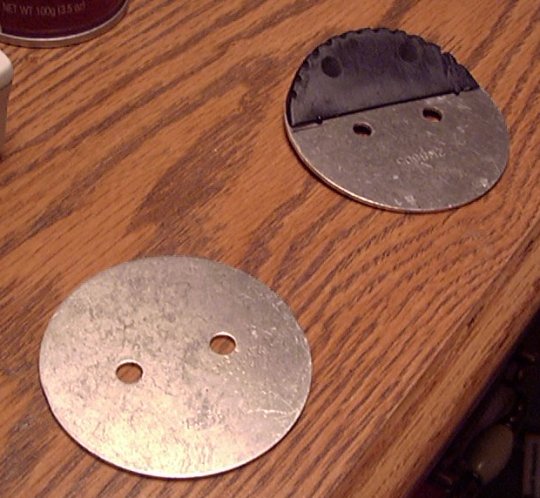 |
| Side-by-side Comparison of Throttle Plates for Automatic Transmission (left) and Manual Transmission (right) 2.7L Applications |
The throttle body for a stock 2.7L engine with the automatic transmission has a 62 mm bore. There are no restrictions in the bore. The throttle plate is just a plate, with no plastic additions. The effective WOT open area for this throttle body is about 2430 mm^2. This represents about a 10% increase over a stock manual throttle body.
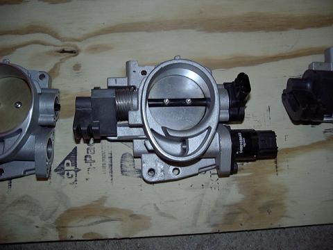 |
| Front view of stock automatic TB |
This means that the effective WOT open area for the manual version of the throttle body is 9% smaller than the effective WOT open are for the automatic version.
 |
| Comparison of 2.7L Throttle Plates - Automatic Transmission Application Placed Over Manual Transmission Application |
Now, for the results. Part-throttle response has become much more responsive. Fuel economy has risen by as little as 2 MPG and as much as 7 MPG. Top-end power effects remain to be seen, but the power curve has shifted up at low-end and mid-range.
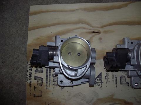 |
| Front view of bored TB |
I have also tested a bored out throttle body that was purchased by Matt (LB3711 of 2GSS.net fame). The body itself is bored out to 65 mm. The throttle plate is just a plate, with no plastic additions. The shaft has been partially removed, which results in a larger opening at WOT. The effective WOT open area for this throttle body is about 2977 mm^2. This represents a 22% increase in opening area over a stock automatic throttle body, and a whopping 34% increase in opening area over a stock manual throttle body.
The bored throttle body also shows improvements, although not as dramatic as was noticed with the stock automatic throttle body. Dynamometer results of all three throttle bodies can be found here. In the meantime, I have included pictures of each throttle body.
You can view a gallery of the different throttle bodies here.
Manifold Tuning Valve Installation with 68HC11-based Controller
The 2001 JR body cars with the 2.7L engine also came with something called a manifold tuning valve (MTV). Basically, what this valve does is change the resonant frequency inside the the intake manifold, depending on whether the valve is shut or not. When the valve is open, the power peak shifts upward. When the valve shuts, the resonance frequency of the intake manifold changes, resulting in a downward shift of the power peak. My engine does not have this valve installed.
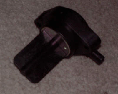 |
| Side View of 2.7L V-6 Manifold Tuning Valve |
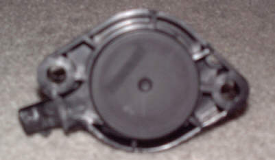 |
| Outer View of 2.7L V-6 Manifold Tuning Valve |
My educated guess, along with data optained from DodgeIntrepid.net, indicates that the MTV ought to be active at greater than 35% throttle opening. Further, as the MTV is activated, the MTV ought to be shut between 3000 RPM and 4300 RPM, and then open up between 4300 RPM and 5800 RPM. Once past 5800 RPM, the MTV ought to be shut again. At 3800 RPM with the MTV open (or with no MTV), the 2.7L engine develops about 180 ft-lbf of torque. With the MTV shut, the engine develops about 195 ft-lbf of torque.
To date, the results of retrofitting the MTV to my engine have been noticably good. I've controlled this valve with a Motorola M68HC11 microcontroller, that gets input from the throttle position sensor and the crankshaft position sensor. I have dynomometer results of the MTV as being open all the time, and as being shut all the time. I have optimized the HC11 program, and at the next available opportunity, I will run the improved HC11 program on the dynomometer.
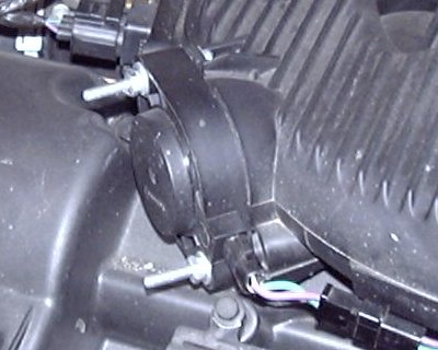 |
| 2.7L V-6 Manifold Tuning Valve Installation |
MSD Stacker-8 Ignition
The MSD Stacker-8 is an aftermarket capacitive-discharge ignition system that provides more spark power to each spark plug. This will provide a more powerful spark, ensuring reliable ignition under boost conditions. Since the 2.7L engine uses a coil-on-plug ignition system, the traditional MSD 6AL (or similar) ignition cannot be used.
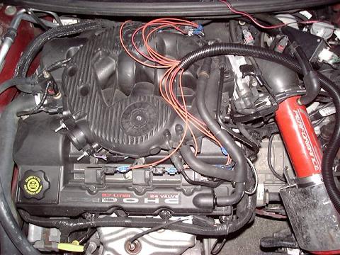 |
| MSD Stacker-8 Wire Harness Rough Installation |
Installation of the wiring harness to the individual coils is the hardest part of actually getting the Stacker-8 to work, and took me about an hour to complete. Actually locating a mounting spot is proving to be one hell of a job. I cannot use the same spot for the Stacker-8 as I did for the MSD 6AL on my 2000 Limited, since that area is taken up by a vacuum reservoir. I cannot mount the Stacker-8 in the area that the TCM normally takes up, because it's too large to fit properly. I have rested the module in that area for now, but I will have to fabricate a mounting plate for the module.
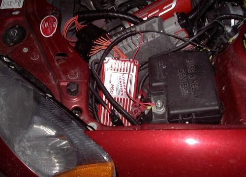 |
| MSD Stacker-8 Module Rough Installation |
I have noticed a slight improvement in tip-in and part-throttle response. Dynamometer results will be forthcoming. I did not get a chance to test this unit on the dynamometer during the last dyno run because the unit itself proved to be defective and had to be shipped back to Summit Racing for a replacement.
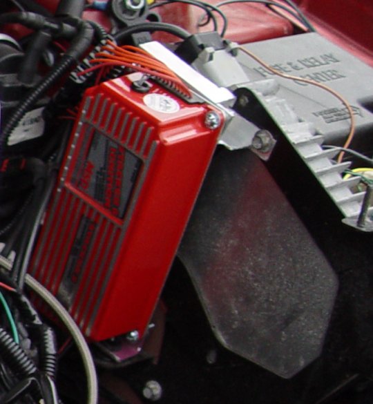 |
| MSD Stacker-8 Module Permanent Installation |
This modification was removed after I read about how this Stacker-8 ignition could burn out stock Chrysler PCMs. Also, MSD no longer offers this unit for sale on their website.
TC SportLine Carbon Fiber Hood
The TC SportLine Carbon Fiber Hood was made for me as part of a group buy. This was, to my knowledge, the first group buy ever for a CF hood for the 2nd generation Stratus/Sebring sedan/convertible. The hoods were finalized in 2004, and I received mine in 2005. The CF hood was noticably lighter than the stock hood, though 35 pounds for a stock hood is fairly light to begin with.
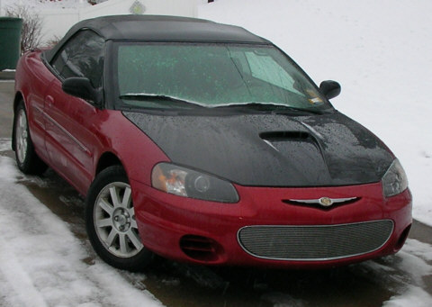 |
| New Carbon Fiber Hood |
Left-Hand and Right-Hand Cylinder Bank Air/Fuel Gauges
Part of getting a decent turbocharged setup is knowing how the engine is burning fuel. This is also important for normal tuning. With that in mind, I set out to install the air/fuel gauges I had bought for my old Limited. However, I didn't want to put them on the A-pillar, since I had that space planned for something else.
I looked around, and saw something that had caught my eye. There is an aftermarket Honda instrument cluster gauge pod that is offered through most major aftermarket Honda supporters. The pod allowed the installation of two gauges on either side of the instrument cluster, and I thought that was a good idea when I saw it.
So, I got a couple of gauge cups, and started cutting into my existing instrument cluster bezel. The actual cutting was somewhat tedious, but was not too much of a pain. I used an extra gauge cup to allow me to position the marks in the instrument cluster bezel, so as to make sure they were at the correct angle when viewed from the driver's seat.
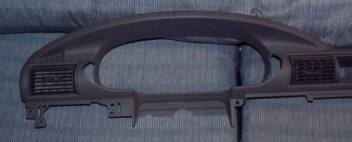 |
| Instrument Cluster Bezel Modification, for Left-Hand and Right-Hand Cylinder Bank Air/Fuel Ratio Gauges |
After that, I used some JB Quik to weld the cups in place, and allowed the assembly to cure overnight. While that was curing, I tapped off the pre-cat O2 sensor signal wires for both the left-hand and right-hand cylinder banks, and ran those wires through the firewall and to the instrument cluster. I used the switched +12 VDC ignition power that operated the instrument cluster, and I used a chassis ground. The air/fuel gauges did not need to be hooked up to the interior lighting circuit, so that was one less wire I had to worry about.
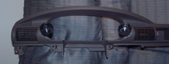 |
| Instrument Cluster Bezel Modification, Showing Gauge Cup for Left-Hand and Right-Hand Cylinder Bank Air/Fuel Ratio Gauges |
When the epoxy cured, I cut holes in the cups large enough to pass nylon wire connectors through. I then installed the bezel. It needed a slight amount of finesse to install, since the gauge cups now got in the way of the steering wheel. Other than that, installation was pretty routine. Now, I used wire connectors so that it would be possible to quickly connect or disconnect the air/fuel ratio gauges. This turned out to be a great idea. I wired up the connector ends so that I could switch the gauges to either cylinder bank, and it would still work correctly.
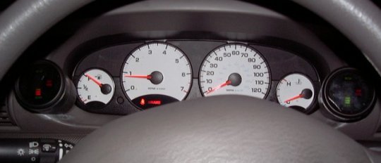 |
| Air/Fuel Ratio Gauge Installation for Left-Hand and Right-Hand Cylinder Banks |
When I was done, I wrapped up the wires, put the rest of the interior panels back on, and took the car for a test drive. I realized something very interesting when I started driving. The O2 sensor signals will continually jump between very lean and very rich; this appears to be how the PCM is able to monitor O2 sensor health while the engine is running. This also enables the PCM to accurately meter fuel while at idle or partial loading. While at WOT, the gauges will read slightly rich, and while coasting with the throttle fully shut, the gauges will read very lean.
You can see more pictures of the air/fuel gauge installation here.
Oil Pressure Gauge
When I suffered a major engine failure in March 2004, I literally had no warning about any pending troubles until I started hearing the timing chain rattling around as a result of the failure of the timing chain tensioner. When that failed, I knew that something serious happened. I did not know the extent of the failure until I took off the oilpan and valve covers, and started inspecting.
When I removed the oilpan and oil pickup tube, I noticed numerous bits of aluminum flash that had somehow gotten into the engine. When I went to clean the oil pickup tube, I also noticed some o-ring bits that had somehow worked their way into the oilpan and against the oil pickup tube screen.
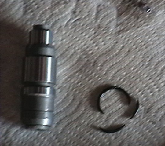 |
| Failed Primary Timing Chain Tensioner and Tensioner O-ring, Along with a Few Bits of Aluminum Flash |
I looked through the factory service manual, trying to get an idea of what could have lost its o-ring. I finally came across a picture of the timing chain tensioner. I took off the tensioner, and confirmed that it had lost its o-ring. Due to the clearance between the tensioner body and its socket in the right-hand cylinder head, oil pressure would have dropped to near zero psig at idle, which is significantly below the 5 psig called for in the factory service manual.
Therefore, I concluded, among other things, that an oil pressure gauge is necessary for this engine. Note what I said - It's not desireable or a good idea, but necessary. I am convinced that too many of these 2.7L engines fail because their owners simply do not realize that their oil pressure had fallen to zero psig due to a timing chain tensioner failure.
With that in mind, I set out to install an oil pressure gauge. I used the tap for the oil pressure switch, and made a few more discoveries. First, the oil pressure switch has a 3/8 " NPT pipe thread, which is larger than what I have seen in the past for other engines. Secondly, the switch is protected by a heatshield. This heatshield deflects heat from the rear exhaust manifold and catalytic converter, but it does make it very hard to perform an installation of a tee for both the oil pressure switch and an oil pressure gauge.
I eventually decided to run a steel braided line from the oil pressure port on the engine block, and install the tee next to the throttle. This made it very easy to install the sender for an electric oil pressure gauge, and the engine wire harness did allow for the repositioning for the oil pressure switch to its new location on the tee. (Oddly enough, due to its present location next to the throttle body, I can also modify the tee to supply a turbocharger with oil... Go figure! ![]() ) I then removed the driver's side A-pillar, and proceeded to fit an aftermarket universal 1-gauge A-pillar pod onto the A-pillar. It took a little grinding and cutting, but the pod was installed.
) I then removed the driver's side A-pillar, and proceeded to fit an aftermarket universal 1-gauge A-pillar pod onto the A-pillar. It took a little grinding and cutting, but the pod was installed.
I then tapped off the power and ground wires I used for the air/fuel ratio gauges, and tapped off an extra wire from the interior lighting circuit. I then ran wiring from the oil pressure sender on the tee, through the firewall, and to the gauge. As with the air/fuel ratio gauges, I used nylon wire connectors for ease of installation and removal.
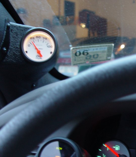 |
| Oil Pressure Gauge Installation Mounted on A-Pillar |
After everything was put together, I ran the engine and noted the results. When the engine is cold, it will put out about 65 psig of oil pressure at idle. When the engine is warm, it will put out about 7 psig of oil pressure at idle. This will rise linearly with engine speed, up to about 3000 RPMs. At that point, the oil pressure relief valve in the oil pump will open, and oil pressure will be limited to about 70 psig. If a large hole opens up in the oil supply, such as would happen when the timing chain tensioner pukes out its o-ring, then oil pressure at idle will drop to near zero, with corresponding lower oil pressures throughout the range of engine speed.
Other trademarks and logos are copyrighted by their various owners.
This website copyright © 2000-2015 Thomas A. Vago. All Rights Reserved.