JR Body (2G Cloud)
CMTC Installation
CMTC Calibration
JA/JX Body (1G Cloud)
CMTC Installation
CMTC Calibration
Swaybar Installation
Cat-Back Exhaust
Induction Tube
MSD 6AL Installation
TPS Modification
Miscellaneous
Waste Money
Car Information
AllData
AllPar
The Society of Automotive Engineers
Car Enthusiasts
2GSS.net
Dakota-Durango
Stratusphere
2GN.Org
Neons.Org
LXForums
Custom Magnums
SebringClub.net
Car Parts Vendors
Car-Part.Com
Mopar Dealer Parts
|
|
How To Install a Capacitive Discharge Ignition
JA/JX (1G Cloud)
This How-To describes how to replace the stock ignition system on a 2.5L Mitsubishi V-6 with a capacitive discharge ignition system. This performance modification will ensure that the fuel/air mixture entering each cylinder is completely ignited, which will ensure that the engine will reliably provide 100% of available power from that fuel/air mixture. This modification is recommended if you are planning on also adding a turbocharger, supercharger, and/or a nitrous oxide injection system. This modification is also recommended if your stock distributor coil fails, as a replacement distributor will cost roughly $675 plus labor. The Autotronic Controls Corporation MSD 6AL ignition controller is presented, along with the Blaster 3 ignition coil.
| Warning |
|---|
| The instruction presented herein is to be used at your own risk. While checked for accuracy, the information in this page may not be 100% accurate, and may not work for your particular vehicle. I will not assume liability for any damages or injuries that result from either properly or improperly following this instruction. Failure to abide by this instruction while performing the indicated task may result in costly damage and/or injury. |
| Note |
|---|
This instruction only applies to the below models:
| Automobile | Model Year | 2.0L
I-4 | 2.4L
I-4 | 2.5L
V-6 |
| Sebring Convertible | 1996-2000 | N/A | No | Yes |
| Cirrus | 1995-2000 | No | No | Yes |
| Stratus | 1995-2000 | No | No | Yes |
| Breeze | 1996-2000 | No | No | N/A |
|
| Caution |
|---|
| A high performance spark plug wire set, that has a wire-wound conductor composition, must be used. In conjunction with any high-energy ignition system, the use of carbon fiber-based spark plug wires will quickly degrade such wires to the point of severe engine misfire. |
| Note |
|---|
| This instruction assumes that the reader is mechanically competent, and has basic knowledge of electronic soldering techniques. If in doubt, seek help. |
- Parts List
| Name | Qty | Mfr/(Location) | P/N | Cost (US$) |
| MSD Controller | | carparts.com | | |
| MSD 6A (Basic) | 1 | carparts.com | 6200 | 139.95 |
| MSD 6AL (Rev Limiter) | 1 | carparts.com | 6420 | 189.95 |
| MSD Blaster 3 Coil | 1 | carparts.com | 8223 | 36.95 |
| MSD Coil Wire Kit | | carparts.com | | |
| 8.0 mm Heli-Core | 1 | | 8403 | 11.95 |
| 8.5 mm Super Conductor | 1 | | 84039 | 13.95 |
| Distributor Cap | 1 | Dealership | MD619050 | 56.50 |
| Ignition Coil Mount | 1 | Auto Parts Store | ??? | $5.00 |
| MOSFET, N-Ch | 1 | TV/VCR Repair Shop | NTE 2389 | 3.99 |
| Resistor, 1K ohm | 1 | RadioShack | 271-1321 | 0.49 |
| Resistor, 10k ohm | 1 | RadioShack | 271-1335 | 0.49 |
| Heat Sink, TO-220 Case | 1 | RadioShack | 276-1638 | 1.49 |
| Heat Sink Mounting Kit, TO-220 Case | 1 | RadioShack | 276-1373 | 1.39 |
| Enclosure, Metal | 1 | RadioShack | 270-235 | 1.99 |
| Grommet, 1/4" | 1 | Auto Parts Store | ??? | 0.49 |
- Consumables
| Name | Mfr/(Location) | P/N | Cost (US$) |
| Wire, 3-pack, 18 gauge, stranded | RadioShack | ??? | 2.99 |
| Heatsink Compound | RadioShack | 276-1372 | 1.99 |
| Electrical Tape | RadioShack | ??? | 3.00 |
| Crimp-On Quick Disconnect 5-Pack | RadioShack | 64-3131 | 1.49 |
| Sealant, RTV, clear, non-conductive | (auto parts store) | ??? | 2.00 |
| Solder, Rosin Core | RadioShack | ??? | 2.00 |
| Sheetmetal Screws, 3/8" Head, 1/2" Length, 1/4" thick | Hardware Store | ??? | 0.25 |
| Washers, Flat, 1/4" | Hardware Store | ??? | 0.25 |
| Washers, Locking, 1/4" | Hardware Store | ??? | 0.25 |
| JB Weld | Auto Parts Store | ??? | 1.99 |
- Tools List
- 8-32 Screw Tap Bit
- 10-32 Screw Tap Bit
- Screw Tap Handle
- Drill
- Drill Bit Set
- #21 Drill Bit
- #29 Drill Bit
- 3/8" Drill Bit
- Torx© Bit Set
- Screwdriver, Phillips Head
- 3/8" drive Metric Socket Set
- 1/4" drive Metric Socket Set
- 1/4" drive Standard Socket Set
- Soldering Gun, 30W
- Wire Strippers
- Vice-Grip Pliers
Procedure
This procedure is divided into three parts.
- Ignition Amplifier Module Construction
- Cut 2 feet of red, black, and green wire.
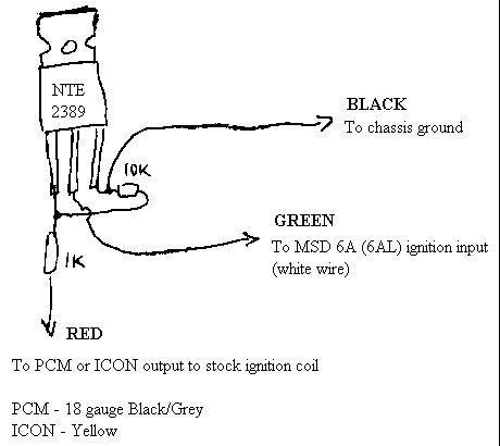 |
| Figure 1: Construction of Ignition Amplifier
|
- Using the above figure, solder together the circuit. Clip the transistor and resistor leads to a length of about 3/8". Mark the wires using strips of masking tape, or some other method.
- Crimp a male connector to the PCM wire.
- Crimp a female connector to the MSD wire.
- Seal the exposed conductors of the completed circuit using the clear, non-conductive RTV, and let cure.
- Drill a 5/32" hole in one of the metal enclosure halves. Drill a 1/4" hole in the other half of the metal enclosure.
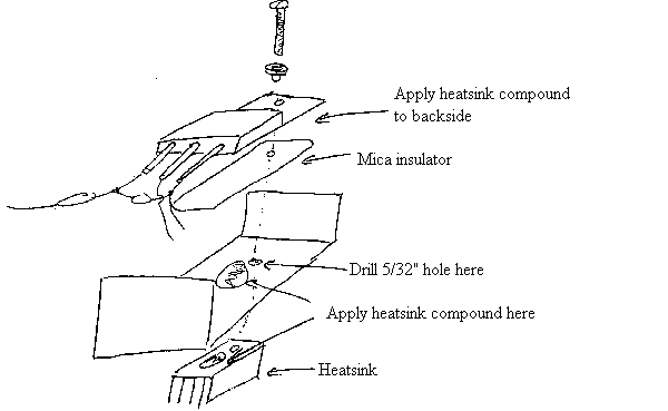 |
| Figure 2: Physical Explosion of Ignition Amplifier Parts Placement
|
- Using the above figure, assemble the circuit and heatsink components.
- Insert the grommet into the 1/4" hole on the other half of the metal enclosure, then pass all three wires through the grommet.
- Assemble the two halves of the metal enclosure, and install the included enclosure screws. Set the completed ignition amplifier module aside.
- Distributor Cap Modification
| Note |
|---|
| This procedure differs from similar modification procedures in that this procedure results in completely bypassing the 5600 ohm carbon resistor normally found in the distributor cap. |
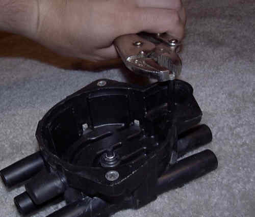 |
| Figure 3: Removal of Stock Coil Electrode from Distributor Cap
|
- Using the vice-grip pliers, remove the stock coil electrode.
- Remove the excess plastic that went around the stock coil electrode.
- Disassemble the MSD Cap-A-Dapt coil tower.
- Using a Dremel tool or a hacksaw, remove the lower skirt from the coil tower body.
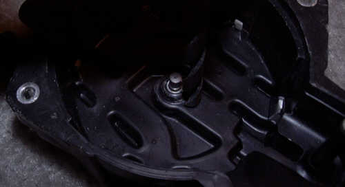 |
| Figure 4: Positioning the 5/32" Drill Bit
|
- Using the 3/8" drill bit, press firmly at the spot indicated in the above photograph. The drill bit should just touch the plastic surrounding the carbon center button.
- Using the #29 drill bit, carefully drill a hole through the spot marked in the previous step.
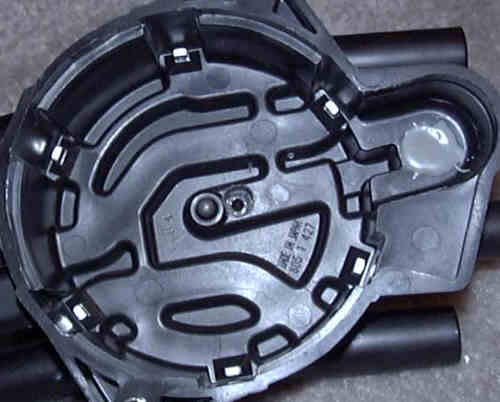 |
| Figure 5: Drilled-Out Hole (note sealed stock coil electrode hole)
|
- Using the 3/8" drill bit, drill out the hole until the drill bit begins to contact metal. Some metal should be visible once the drill bit is removed.
- Using the 8-32 screw tap bit and tap handle, carefully thread out the hole just drilled.
- Thread the screw with the steel wool washer through the hole, from the bottom of the distributor cap. Tighten the screw hand-tight.
- Using the instructions included, mix together a small (about the size of three US quarter-dollar coins) amount of JB Weld.
- Seal up the hole left by the stock coil electrode with a small amount of mixed JB Weld. Hold the mixed JB Weld in place with a small strip of electrical tape.
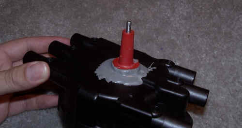 |
| Figure 6: Installing the Coil Tower Body
|
- Apply a good portion of the mixed JB Weld to the bottom of the coil tower body, and place the coil tower body over the screw.
- Install the brass electrode nut, and carefully tighten the nut with a pair of vise-grip pliers. Do not clamp the nut with too much force, or else the nut will develop tooth marks from the pliers.
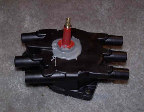 |
| Figure 7: Completed Distributor Cap Modification
|
- Apply the rest of the mixed JB weld to the top of the distributor cap, around the coil tower body. Allow the specified time for the JB Weld to cure.
- Once the JB Weld has cured, remove the electrical tape from the inside of the distributor cap.
- Installation
- Preparation for Work
- With the engine running, turn the front wheels fully to the left.
- Turn off the engine.
- Open and support the hood on the hood prop rod.
- Remove the battery negative cable from the ground stud on the left strut tower.
- Remove the intake air hose or induction tube (if installed).
- Removal of Front Bumper Fascia
- Remove the left and right headlamp assemblies.
- Remove the fasteners holding the grille and bumper fascia to the headlamp adapter assembly.
- If equipped, disconnect the wiring connectors from the left and right foglamps.
- Remove the fasteners securing the right fender inner splash shield to bumper fascia.
- Remove the left fender inner splash shield.
- Reach into each fender and remove two nuts on each side securing the fender to the bumper fascia.
- Reach into the lower radiator opening on the bumper fascia, and remove two fasteners that secure the bumper fascia to the bumper bar.
- Lay a blanket under the bumper fascia.
- Push down on the bumper fascia to disengage the fender studs.
- Slide the bumper fascia forward, and set aside.
- Ignition Controller Physical Installation
| Note |
|---|
| The procedure below deals primarily with the placement of the MSD 6A (6AL) module, and has been developed using the Chrysler Sebring Convertible. There is no guarantee that the location described below will also work for the Chrysler Cirrus, Dodge Stratus, or any other vehicle that uses the Mitsubishi 2.5L V-6. |
- Disconnect the battery positive, then negative cables from the battery.
- Remove the front and rear battery strap hold-down bolts, then remove the battery strap.
- Remove the battery.
- Remove the battery mount bolts, then remove the battery mount.
- Line up the ignition controller vertically so that the coil leads, power, ground, and ignition input wires point up.
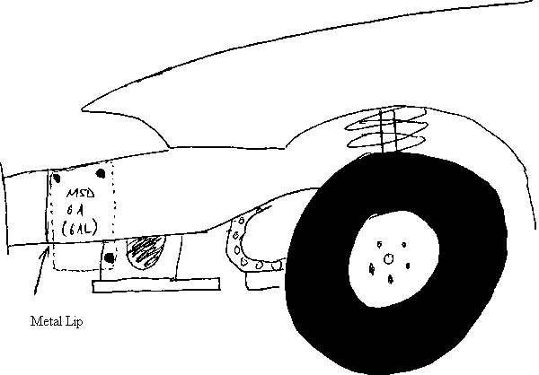 |
| Figure 8: Placement of MSD 6A (6AL) Controller
|
- Flush the ignition controller to the top of the left frame rail, as shown in the above figure.
- Holding the ignition controller in place, use the drill with the #21 drill bit and mark the top forward mount hole position.
- Remove the ignition controller, then drill out the hole marked in the above step.
- Using the 10-32 screw tap bit and tap handle, tap out the hole drilled in the above step.
- Temporarily install the ignition controller, using one of the mounting screws that came with the controller.
- Using the drill and #21 drill bit, mark the positions of the top aft and bottom aft holes. The bottom aft hole may be difficult to reach. If this is the case, use some other method of marking the bottom aft hole.
- Remove the ignition controller, then drill out the holes marked in the step above.
- Using the 10-32 screw tap bit and tap handle, tap out the holes drilled out in the above step.
- Install the rubber isolation bushings in the holes drilled out above. Be sure to firmly snug each bushing.
- Install the ignition controller to the rubber isolation bushings, using the included mounting screws.
- Install the battery mount, then the battery mount bolts.
- Install the battery.
- Install the battery strap, then the battery strap hold-down bolts.
- Install the battery negative, then positive cables onto the battery.
- Installation of Modified Distributor Cap
- Disconnect the TPS and the IAC wiring connectors from the throttle body.
- Disconnect the emissions hose from the throttle body.
- Remove the throttle cable and speed control cable (if equipped) from the throttle body.
- Remove the throttle body, and set aside.
| Warning |
|---|
| The following four steps must be followed exactly. Failure to comply may result in severe engine misfire, and may even destroy the engine if it is started. |
- Carefully remove all ignition wires from the stock distributor cap, making sure their relative positions are not disturbed.
- Carefully remove the stock distributor cap, and set aside.
- Carefully install the modified distributor cap.
- Carefully install each ignition wire to its proper terminal on the modified cap.
- Install the throttle body.
- Re-attach the speed control cable (if equipped) and the throttle cable to the throttle body.
- Re-attach the emissions hose to the throttle body.
- Re-attach the IAC and TPS wiring connectors to the throttle body.
- Installation of Aftermarket Ignition Coil
- Position the Blaster 3 coil in the ignition coil bracket, and tighten the bracket until the Blaster 3 coil can just barely move in-and-out of the bracket.
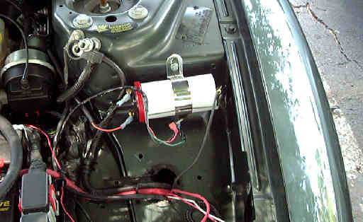 |
| Figure 9: Placement of Blaster 3 Coil (Blaster 2 shown)
|
- Using the above picture and the ignition coil bracket as guides, drill two holes in the front of the left strut tower.
- Install the Blaster 3 coil, using the sheetmetal screws and washers. Before the screws are installed, place (in this order) a lockwasher, then a flat washer, on the screw.
- Ignition Controller Electrical Installation
- Route the wires from the ignition controller through the access hole that the battery leads pass through.
- Remove the nut holding the battery positive cable on the PCM/TCM/PDC assembly, then install the MSD 6A (6AL) B+ wire on the battery positive cable stud. Re-install the nut on the battery positive cable stud.
| Caution |
|---|
| Failure to comply with the below two step will result in engine malfunction. |
- Carefully open up the wiring harness coming from the rearward PCM connector, and locate a black/grey wire and a dark green/orange wire in this harness.
- Carefully splice in the MSD 6A (6AL) switched ignition power wire to the dark green/orange wire. DO NOT CUT THE DARK GREEN/ORANGE WIRE!
- Cut the black/grey wire, and install a female crimp-on blade connector to the PCM side of the cut wire. Install a male crimp-on blade connector to the engine side of the cut wire.
- Connect the female PCM blade connector in the wiring harness to the male PCM blade connector on the ignition amplifier.
| Note |
|---|
| The male PCM blade connector that connects to the stock ignition coil should be wrapped to protect it from the elements, but may be left alone. Since this wire no longer connects to anything, the stock distributor coil is effectively isolated from the ignition system. |
- Find a suitable ground for the ground wire of the ignition amplifier, and connect the ground wire to that point.
- Find a suitable ground for the ground wire of the MSD 6A (6AL), and connect the ground wire to that point.
- Crimp a male connector onto the MSD 6A (6AL) ignition signal wire, then connect the female MSD connector on the ignition amplifier to the male connector on the MSD 6A (6AL).
- Place the ignition amplifier into the duct underneath the left headlamp assembly.
- Install the ignition coil wire on the Blaster 3 coil and the ignition coil tower on the modified distributor cap. It may be necessary to re-position the Blaster 3 coil within the ignition coil bracket.
- Once the ignition coil wire is installed, tighten the ignition coil bracket until the Blaster 3 coil is snug.
- Installation of Front Bumper Fascia
- Making sure that the styrofoam energy absorber is properly positioned inside the bumper fascia, carefully rest the bumper fascia on the bumper bar.
- Manipulate the bumper fascia to engage the fender studs, then install the nuts securing the fascia to the fenders.
- Install the fasteners securing the bumper fascia to the bumper bar.
- Install the left fender inner splash shield.
- Install the fasteners securing the right inner splash shield to the bumper fascia.
- If equipped, re-connect the wiring connectors to the left and right foglamps.
- Install the fasteners holding the grill and bumper fascia to the headlamp adjuster assembly.
- Install the left and right headlamps.
- Vehicle Restoration
- Install the intake air hose or induction tube.
- Install the battery negative cable on the ground stud on the left front strut tower.
- Start the vehicle, and verify that the engine runs smoothly.
|


