JR Body (2G Cloud)
CMTC Installation
CMTC Calibration
JA/JX Body (1G Cloud)
CMTC Installation
CMTC Calibration
Swaybar Installation
Cat-Back Exhaust
Induction Tube
MSD 6AL Installation
TPS Modification
Miscellaneous
Waste Money
Car Information
AllData
AllPar
The Society of Automotive Engineers
Car Enthusiasts
2GSS.net
Dakota-Durango
Stratusphere
2GN.Org
Neons.Org
LXForums
Custom Magnums
SebringClub.net
Car Parts Vendors
Car-Part.Com
Mopar Dealer Parts
|
|
How To Install a CMTC
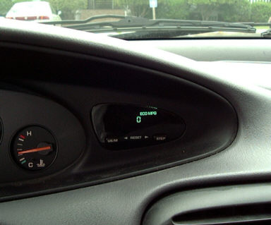
JA/JX (1G Cloud)This How-To facilitates the installation of a Compass/Mini-Trip Computer (CMTC) into a Chrysler Cirrus/Chrysler Sebring Convertible/Dodge Stratus/Plymouth Breeze. The CMTC is normally a factory option, and allows the driver to display temperature and direction (8-point), average fuel economy, instantaneous fuel economy, current range to empty fuel tank, trip odometer, and elapsed time since last CMTC reset. In addition, the CMTC display can be cycled off.
| Warning |
|---|
| The instruction presented herein is to be used at your own risk. While checked for accuracy, the information in this page may not be 100% accurate, and may not work for your particular vehicle. I will not assume liability for any damages or injuries that result from either properly or improperly following this instruction. Failure to abide by this instruction while performing the indicated task may result in costly damage and/or injury. |
| Note |
|---|
This instruction only applies to the below models:
| Automobile |
Model Year |
2.0L
I-4 |
2.4L
I-4 |
2.5L
V-6 |
| Sebring Convertible |
1996-2000 |
N/A |
Yes |
Yes |
| Cirrus |
1995-2000 |
Yes |
Yes |
Yes |
| Stratus |
1995-2000 |
Yes |
Yes |
Yes |
| Breeze |
1996-2000 |
Yes |
Yes |
N/A |
|
| Note |
|---|
| This instruction assumes that the reader has a basic knowledge of soldering and general wire-working practices. If in doubt, consult an electronics technician or professional car electronics installer. |
- Parts List
| Note |
|---|
| The entire instrument cluster hood and bezel must be purchased (vice purchasing just the bezel itself) because that is currently the only way to get the bezel that has the CMTC mount and window. The bezel itself is actually glued into the hood. Now, the part number listed above is for an agate hood (dark grey). If you don't have an agate interior, you'll have to contact your local Chrysler parts department to find a hood that matches the color of your own interior. And if you do so, please email me with the part number so that I can add it here. |
| Name | Mfr/(Location) | P/N | Cost ($US) |
| CMTC Module | DaimlerChrysler | 4671342-AD | 165.75 |
| Hood & Bezel, Instrument Cluster | DaimlerChrysler | | |
| Agate w/ TRAC OFF | | QW121AZ-AA | 207.40 |
| Agate w/out TRAC OFF | | QW121C3-AA | 207.40 |
| DB-9 Female Solder Kit | RadioShack | 276-1428A | ~2.00 |
| 6 Position Male Nylon Connector Kit | RadioShack | 274-226 | 1.39 |
| 6 Position Female Nylon Connector Kit | RadioShack | 274-236 | 1.39 |
| Sheet Metal Screws (4), 0.5" length by 0.25" head | (Hardware Store) | | ??? |
- Consumables
| Note |
|---|
| If 9-conductor cable is not available, buy a computer serial cable instead. |
| Name | Mfr/(Location) | P/N | Cost ($US) |
| Solder, 60/40 Rosin Core | RadioShack | ??? | ??? |
| 9-Conductor Cable, 6 feet | RadioShack | ??? | ??? |
| Friction Tape | (Hardware Store) | | ??? |
| Sealant, Silicone Adhesive, Clear | (Hardware Store) | | 2.00 |
- Tools List
- Soldering Gun, 30 W
- Screwdriver, Phillips Head
- Rachet, 3/8" Drive
- Socket, 15 mm, 3/8" Drive
- Wire Strippers
- Razorblade or sharp knife
Procedure
This procedure is divided into three parts.
Preparing the CMTC for installation
- Cut about 2 feet of the 9-conductor cable, and separate out the white, black, violet (purple), orange, and red wires.
- Solder the female pins from the 6 position female connector kit onto one end of each of the wires.
- Twist the white and violet (purple) wires so as to give about three to four twists per inch.
| Note |
|---|
| The pin locations will be marked on the back of the nylon connector, but the markings will just barely be visible. |
- Insert the pinned ends of the wires into the connector in the following sequence:
| Wire | Purpose | Pin Position |
| Violet (purple) | + CCD Bus | 1 |
| White | - CCD Bus | 2 |
| Black | Ground | 4 |
| Orange | Fused Ignition | 5 |
| Red | Fused Battery | 6 |
- Wrap the wire harness with the friction tape, leaving about three inches of wire exposed at the end.
- Cut about six inches of the 9-conductor cable, and separate out the white, black, violet (purple), orange, and red wires.
- Solder the male pins from the 6 position male connector kit onto one end of each of the wires.
- Solder the female pins from the DB-9 female solder kit onto the other end of each of the wires.
- Twist the white and violet (purple) wires so as to give about three to four twists per inch.
| Note |
|---|
| The pin locations will be marked on the back of the nylon connector, but the markings will just barely be visible. |
- Insert the male-pinned ends of the wires into the connector in the following sequence:
| Wire | Purpose | Pin Position |
| Violet (purple) | + CCD Bus | 1 |
| White | - CCD Bus | 2 |
| Black | Ground | 4 |
| Orange | Fused Ignition | 5 |
| Red | Fused Battery | 6 |
- Wrap the harness with friction tape, leaving about an inch from the female pins.
| Warning |
|---|
| The CMTC module is an electronic device that is susceptible to electrostatic shock damage. Static electricity on the human body has the potential to damage the CMTC module. Touch a metal ground before working with the CMTC module, and periodically while handling the CMTC. Failure to abide by this warning could result in a $165.70 paperweight. |
- Insert the female pins onto the CMTC module male pins, using the below diagram and table.
 |
| CMTC Pin Diagram when CMTC module is viewed from rear
|
| Wire | Purpose | Pin Position |
| Violet (purple) | + CCD Bus | 1 |
| White | - CCD Bus | 2 |
| Black | Ground | 5 |
| Orange | Fused Ignition | 6 |
| Red | Fused Battery | 7 |
- Seal the female pins into place with the silcone sealant, and let the sealant cure.
| Warning |
|---|
| Use care with the following step, as the CMTC mount plastic is prone to shatter if too much force is applied. |
- Run out the CMTC mounting screw holes on the new hood, using one of the four screws.
| Note |
|---|
| Do not cover the front of the CMTC module with the tape. |
- Once the silicone sealant cures, tape about 2 inches of the wiring harness to the back of the CMTC module using the friction tape.
- Install the CMTC module into the new hood, using the four screws.
Installing the CMTC into the vehicle
- Disconnect the negative battery cable from the ground stud on the left shock tower.
- Remove the fuse cover, and set aside.
- Remove the dashboard center bezel by pulling it out evenly and carefully, and set aside.
- At the left end of the dash, remove the single screw securing the hood to the dash.
- Remove the four screws from the center that hold the hood to the dash.
- Tilt the steering wheel to its lowest position.
- Pull the hood straight back.
- Remove the hood.
- In sequence, pop out the three vent air directors out of the hood, and install them in the new hood.
- Remove the four screws securing the instrument cluster to the dash.
- Withdraw the instrument cluster from the dash, and disconnect the wiring connectors from the instrument cluster.
- Remove the instrument cluster, and set aside.
- Carefully peel back the friction tape from both wiring harnesses up to where the harnesses join together.
| Warning |
|---|
| Failure to exercise caution during the following step may render the instrument cluster useless. DO NOT CUT ANY WIRES! |
| Note |
|---|
| In the "Instrument Cluster Harness Wire" column, the color after the slash denotes the color of a small stripe, visible when viewing the wire. |
- Splice in the bare-wire end of the fabricated CMTC harness with the female connector to the instrument cluster harness, using the below table. The splice point should be where the two instrument cluster wiring harnesses join together. Solder splices are recommended.
| Assembled Harness Wire | Purpose | Instrument Cluster Harness Wire |
| Violet (purple) | + CCD Bus | Violet/Brown (Twisted Pair) |
| White | - CCD Bus | White/DkBrown (Twisted Pair) |
| Black | Ground | Black/DkOrange |
| Orange | Fused Ignition | Red/Violet |
| Red | Fused Battery | Pink/Red |
- Wrap each of the two original instrument cluster wiring harness with friction tape up to the point where they join.
- Wrap the junction of the three wiring harnesses with friction tape, so as to leave no exposed wires.
- Take the instrument cluster and reconnect the two wiring connectors.
- Route the CMTC wiring harness to the right of the instrument cluster, then install the instrument cluster using four screws.
- Place the new hood on the dash, then reach through the instrument bezel and connect the CMTC wiring connectors.
- Carefully push the wiring harness into the dash, then position the hood on the dash.
- Reconnect the negative battery cable.
- Turn the ignition to the "On" position. The CMTC should briefly light up all segments, then show the temperature and compass heading, along with a "C".
| Note |
|---|
| If "NO CCD" is displayed from the instrument cluster odometer, turn the ignition off, and disconnect the CMTC wiring connectors. Turn the ignition back to "On". If the odometer display shows the odometer, re-check the CMTC wiring harness connections to the male connector and to the CMTC module. Otherwise, re-check the female connector and the splices. |
- Turn on the parking lights, and verify that the CMTC display dims when the dimming knob is adjusted.
- Turn the ignition to the "Off" position.
- Firmly press the hood onto the dash to seat the fasteners.
- Install four screws that hold the hood center to the dash.
- Install the one screw that holds the left of the hood to the dash.
- Install the center bezel by firmly pushing it in until the fasteners engage.
- Install the fuse cover by firmly pushing it until the fasteners engage.
CMTC Calibration and Setting Magnetic Variance
- Turn the ignition to the "On" position.
- Using the CMTC "Step" button, cycle the CMTC display as necessary to display the compass and temperature display.
- Simultaneously press the CMTC "US/M" and "Step" buttons. The magnetic variance display should appear.
- Using the below map, press the CMTC "Step" button to set the correct magnetic variance for your region. The CMTC will return to the compass and temperature display after 5 seconds of no button activity.
 |
| CMTC Magnetic Variance Diagram
|
- Drive the vehicle to a wide open area free of any large metal object, then slowly (around 5 MPH) drive in a circle about three times, or until the "C" goes away from the compass display.
You're Done!!!
 |
| Stratus ES Compass/Mini-Trip Computer Installation
|
|


