JR Body (2G Cloud)
CMTC Installation
CMTC Calibration
JA/JX Body (1G Cloud)
CMTC Installation
CMTC Calibration
Swaybar Installation
Cat-Back Exhaust
Induction Tube
MSD 6AL Installation
TPS Modification
Miscellaneous
Waste Money
Car Information
AllData
AllPar
The Society of Automotive Engineers
Car Enthusiasts
2GSS.net
Dakota-Durango
Stratusphere
2GN.Org
Neons.Org
LXForums
Custom Magnums
SebringClub.net
Car Parts Vendors
Car-Part.Com
Mopar Dealer Parts
|
|
How To Build The Mark II Induction Tube
JA/JX (1G Cloud)
This How-To facilitates building and installing a home-made induction tube for Chrysler Sebring Convertible/Chrysler Cirrus/Dodge Stratus vehicles equipped with the Mitsubishi 2.5L V-6 engine. This tube will give a noticable performance improvement over the stock intake assembly, and is estimated to raise peak horsepower by 5 HP. For the instructions on how to build the older Mark I induction tube, click here.
| Warning |
|---|
| The instruction presented herein is to be used at your own risk. While checked for accuracy, the information in this page may not be 100% accurate, and may not work for your particular vehicle. I will not assume liability for any damages or injuries that result from either properly or improperly following this instruction. Failure to abide by this instruction while performing the indicated task may result in costly damage and/or injury. |
| Note |
|---|
This instruction only applies to the below models:
| Automobile | Model Year | 2.0L
I-4 | 2.4L
I-4 | 2.5L
V-6 |
| Sebring Convertible | 1996-2000 | N/A | No | Yes |
| Cirrus | 1995-2000 | No | No | Yes |
| Stratus | 1995-2000 | No | No | Yes |
| Breeze | 1996-2000 | No | No | N/A |
|
| Note |
|---|
| This instruction assumes that the reader is mechanically competent. If in doubt, seek help. |
- Parts List
| Name | Qty | Mfr/(Location) | P/N | Cost ($US) |
| Filter, Conical, K&N, 3.5" ID | 1 | (auto parts store) | ??? | 49.00 |
| Elbow, 45°, 3" ID, ABS, M/F | 2 | (hardware store) | ??? | 2.50 |
| Pipe, 3" ID, ABS, 10 ft | 1 | (hardware store) | ??? | 12.00 |
| Adapter, Rubber, 3" ID to 2" ID | 1 | (hardware store) | ??? | 7.00 |
| Union, straight, 3/8"-3/8" | 2 | (hardware store) | ??? | 0.50 |
- Consumables
| Name | Mfr/(Location) | P/N | Cost ($US) |
| Cement, ABS Plastic | (hardware store) | ??? | 1.49 |
| Hose, 3/8" ID, Fuel Line, 24" length | (auto parts store) | ??? | 3.00 |
| Superglue | (auto parts store) | ??? | 1.50 |
| Sealant, RTV | (auto parts store) | ??? | 2.00 |
- Tools List
- Hacksaw
- Dremel Tool
- High-Speed Cutting Bit Set
- Screwdriver, Phillips Head
- Ruler
Procedure
| Warning |
|---|
| Avoid breathing the dust particles from cutting and grinding ABS plastic. A filter mask is recommended for wear. |
| Caution |
|---|
| When cutting ABS tubing, be sure to keep the cut as straight as possible. Also, keep the cut as close to 90° (perpendicular) as possible; angled cuts will complicate assembly. |
- Measure 7.5" of ABS pipe, then cut off.
| Note |
|---|
Ensure that the next step produces an even chamfered surface with about a 45° angle on the outer edge.
The inner diameter of the tube may not be flush with the inner diameter of the elbows, when the tube is joined to the female end of the elbow. Therefore, slight chamfering of the inner pipe diameter may be necessary to ensure a flush fit. |
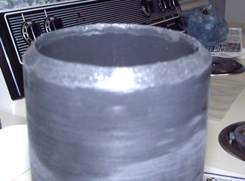
- Chamfer the outer edges of the 7.5" tube as shown in Figure 1 below.
 |
| Figure 1: Chamfered Edge of Tube
|
- Join the tube to the female end of one of the elbows, and check the flush of the union. If the inner diameters aren't flush, pull the tube off, and chamfer the inner edge. Repeat this step until the internal surfaces are flush. Repeat for the other end of the tube.
- Wash the 7.5" tube and the two elbows, then let air-dry.
- Following the instructions on the label for the ABS cement, join one end of the tube to the female end of one of the elbows, and let set.
| Note |
|---|
| The outer edge of the female elbow should have 45° tick marks. The next step requires that the tube be joined to the second elbow in such a way so as to have a 45° radial offset. |
- Following the instructions on the label for the ABS cement, join the other end of the tube to the female end of the other elbow so that there exists a 45° radial offset as shown in Figure 2 below.
 |
| Figure 1: Chamfered Edge of Tube
|
- Set the tube assembly aside and let the ABS cement cure for the time specified with the cement instructions.
| Note |
|---|
| It is not necessary to remove the stock air filter assembly at this time. |
- After the tube assembly has cured, take the tube assembly out to the vehicle, and test-fit the tube assembly. The outboard end of the tube assembly should point down when the inboard end is matched to the throttle body.
- Find a spot on the tube portion of the tube assembly for the crankcase breather line, and mark it.
- Drill out a hole large enough to fit a 3/8" union, using the mark made in the step above.
- Wash the tube assembly, then towel-dry it.
- Superglue the 3/8" union into the hole, and allow it to set.
- Seal the base of the 3/8" union (where it joins the tube assembly) using the RTV sealant.
- Set the tube assembly aside to allow the RTV to cure.
- Attach the 3" to 2" rubber adapter to the intake end of the tube assembly, and secure with the included hose clamp.
- Attach the 3/8" fuel line to the 3/8" adapter on the tube assembly.
- Attach the cone filter to the outboard end of the tube assembly, and secure with the included hose clamp.
- Remove the battery negative cable from the left strut tower.
- Take the intake assembly off the air cleaner.
- Loosen the hose clamp on the stock intake assembly, then detach it from the throttle body.
- Remove the crankcase breather line from the resonator tube portion of the stock intake assembly, then set the intake assembly aside.
- Remove the air filter element, then remove the lower air filter housing.
- Loosen the hose clamp associated with the 2" end of the tube assembly, then fit the end onto the throttle body.
- Adjust the tube assembly so that the cone filter points downward and fits in the engine bay.
- Secure the throttle body hose clamp.
- Cut the 3/8" fuel line as required to comfortably meet the crankcase oil breather hose, then attach the fuel line to the crankcase oil breather hose using a 3/8" union.
- Re-connect the battery negative cable on the left strut tower.
Pictures
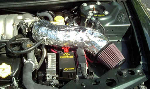
Here is a picture of my induction tube as it appears installed in the vehicle. The foil wrapping is a Mylar insulation attached with foil tape, and gave no noticable advantage. The ABS plastic seems to adequately insulate the intake air by itself. Note the curvy shape of the tube itself. The tube itself was, of course, replaced with the Dreamspeed Performance Engineering induction tube.
 |
| Mark II Air Induction Tube
|
|

